This document is in slide mode. t to toggle h for help
Motion capture (measuring movements)
An introduction to measurement
Measurements and the associated instrumentation is called metrology.
We are often looking to identify the state of an object or body, that is information about position, velocity, acceleration, and the variables that cause these to change, such as forces and torques.
We can consider instrumentation in two potential categories
Intrinsic: A measurement at a single point using a sensor attached to the body.
measures, acceleration, angular velocity, temperature, pressure, magnetic field, sound pressure, current
Extrinsic : A relative measurement between two coordinate systems
measures, velocity, position (e.g. relative to ground), force (across the sensor), voltage
What might go in this table?
Physiological sensor
property
heart rate
muscle activity (also brain)
internal human/animal organs
blood flow or blood density
others
Motion capture
There are broadly two approaches to measuring movements such as gaits, the first approach tends to be camera based where measurements are made with respect to markers or sensors in the room and on the body. The second approach is intrinsic in that it does not (in theory) confine the individual to a motion capture laboratory or a gait laboratory.
Absolute metrics (camera, time of flight or triangulation)
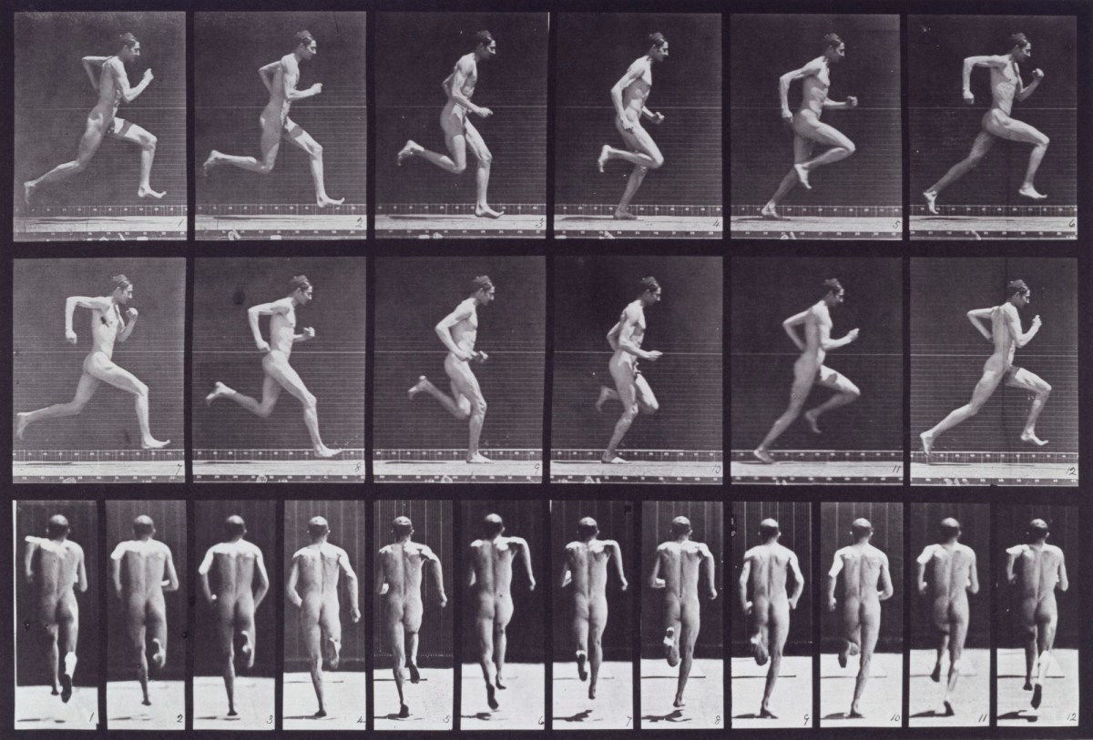
Eadweard Muybridge's cameras
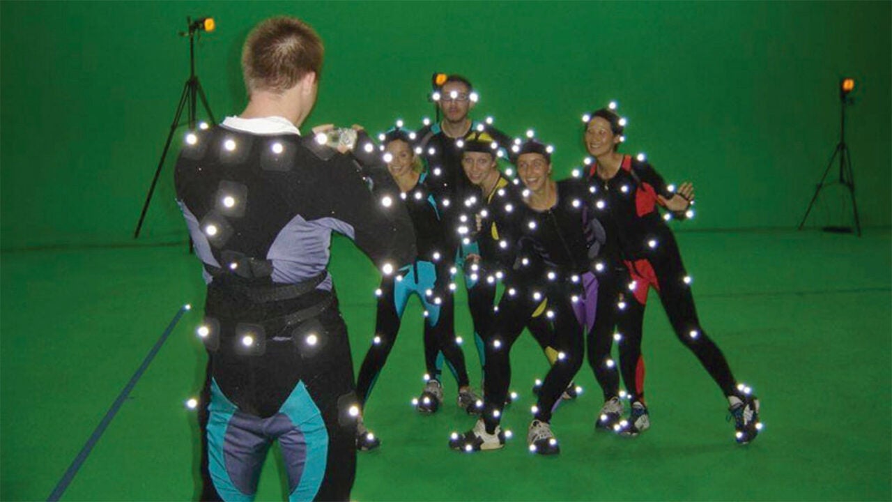
Passive (optical) markers e.g. VICON markers and IR cameras
Active markers e.g. Ultrasound beacons, infrared emitters
Image processing techniques (e.g. Kinect camera )
Intrinsic (Inertial methods)
Accelerometers and gyroscopes (search for Xsens.com)
(research gate)
Eadweard Muybridge
(royal academy)
Muybridge's 24 camera system
tracking methods
Identify a marker or sensor relative to base station
HTC Vive lighthouse (active markers)
Codamotion (active markers)
Vicon (passive markers)
Qualisys
Qualasys
Vicon like methods
Problems, obscured markers, accuracy vs area/volume of measurement, resolution of individual markers in each camera image.
Minimal system needs about 4 cameras, a good system will have up to 16. CGI will use many more.
More cameras mean, 1) possibly greater accuracy (more measurements of the variable), 2) less chance of obscured markers, 3) larger area coverage. Multiple cameras need greater care with calibration.
Uses Gait diagnosis and evaluation
GCI for games and movies (e.g. polar express, Lord of the Rings, Rise of the Planet of the Apes, Tintin)
Usually estimates positions and orientations of markers and marker frames
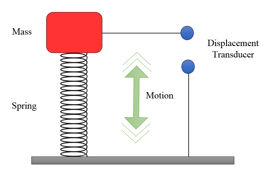
Inertial methods
The inertial sensors are often called IMU (inertial measurement units), and typically measure
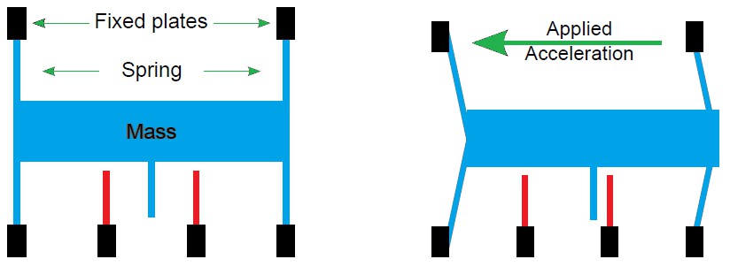
Linear acceleration (accelerometers)
Angular velocity (gyroscope)
Earth and other magnetic fields (magnetometer)
Acceleration and angular velocity are intrinsic measurements, i.e. they only need to be measured in the coordinate frame of the sensor.
Problem: Often the accelerometer, gyroscope and magnetometer measurements are integrated so as to estimate position and orientation of the sensor. This integration often leads to problems such as integral drift, sensitivity to disturbances of the magnetic field, or the relative weighting of the three sensors leading to noisy measurements.
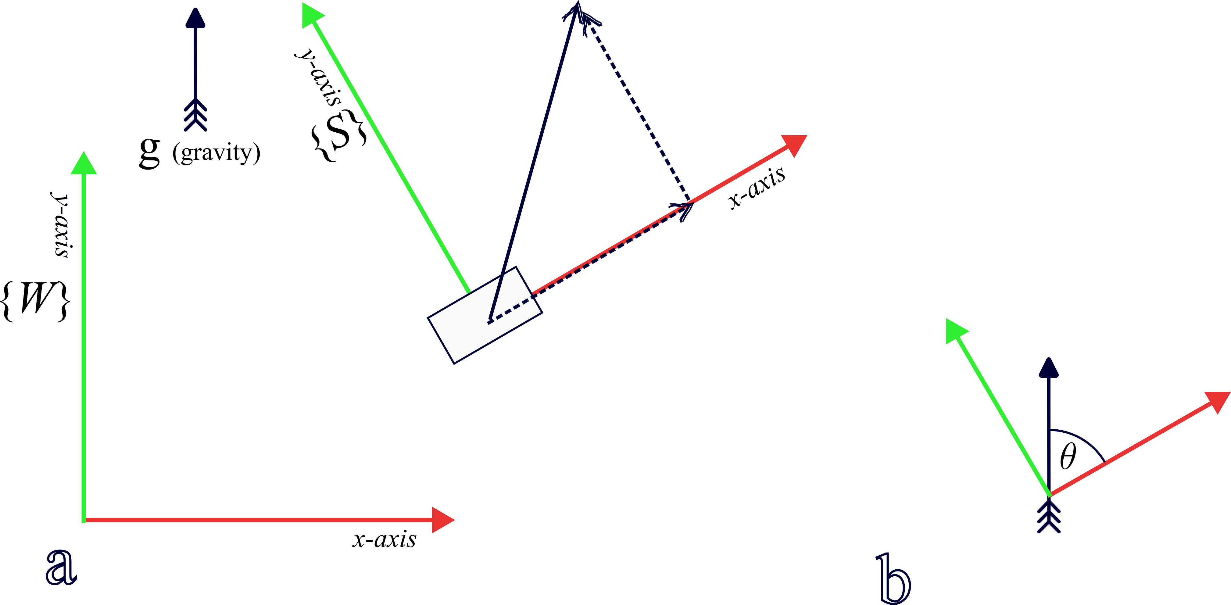
Figure 1: (a) World frame of reference and sensor frame of reference. (b) Sensor to vertical angle
In the figure above we are only interested in the relative orientation of frames {$W$} and {$S$}. There are several ways to calculate the components of a vector measured in frame {$S$} as components of frame {$W$}. One way is with a matrix $R$ (known as a rotation matrix)
In the above example we would like to know the angle $\theta$ between the sensor x-axis and the gravity vector. The sensor will measure gravity plus any additional acceleration as a vector and report its three components. The big assumption we will make is that the sensor moves in a vertical plain and as a result the z-axis component of acceleration $a_z$ is small.
The angle is can be calculated from
\[ \tan\theta=\frac{a_y}{a_x} \]
Most programming languages provide an 'atan2' function so that theta can be estimated in the range $-180^\circ\le\theta\le 180^\circ$
This is not enough to work out the orientation of the sensor. For this information we need to consider information from the magnetometer and the gyroscope. It is then possible to estimate the full orientation usually given as a rotation matrix $R$ or an orientation quaternion $q$ (see (http://www.cybernetia.co.uk/dnb/racequaternions.html) for details)
In an ideal world
accelerometer (when not moving) gives up
magnetometer (when not moving, away from metals and magnets), gives North
gyroscope angular velocity can be integrated to refine the estimates of orientation.
This is a reconstruction problem where there are three differing ways to calculate the imu orientation, and give an indication of its position since it was turned on. In practice the integration of these information channels is a hard problem.
Sensor angular velocity
In the example above we may also want to know the rate of change of the angle $\theta$ This is information that is measured directly by the accelerometer and reported as the angular velocity around the $x,y$ and $z$ axes ($\omega_x, \omega_y, \omega_z$). Once again, if we can assume that the sensor is rotating in the vertical plane, then $\omega_x=\omega_y=0$ and the angular velocity $\omega_z$ gives us the angular velocity of $\theta$
IMU Summary
IMU (inertial measurement unit) can be considered to have intrinsic sensors, typically accelerometer, gyroscope, and possibly magnetometer, temperature and pressure sensors.
If any IMU is not rotating with respect to the world frame and is either stationary or moving with a constant linear velocity it will be reporting the components of gravity.
If an IMU is away from any metal or magnets it may be able to measure the earth's magnetic field.
Earths magnetic field measurement is small and easily disturbed, by movement, metals and magnets.