Stress, strain and strength of materials
This sections will cover
- Stress and Strain (Hooke's law, strain energy)
- Stiffness (Structures with multiple load paths)
- Stress concentration
be distributed.
Biomaterials
Some material properties
| Material | Tensile strength($\sigma_\mathrm{f}$) | Youngs modulus (E) | Density ($\rho$) |
|---|---|---|---|
| MPa | GPa | $Mgm^{-2}$ | |
| trabecular bone | 10.4-14.8$^*$ | ||
| cortical bone | 70$^+$ | 18.6-20.7$^*$ | |
| cortical bone (transverse) | 5-13$^+$ | ||
| ABS M30 (3D printer) | 31 [1] | 2.23 | 1.04 |
| ABS M30 (transverse) (3D printer) | 26 [1] | 2.18 | 1.04 |
| Carbon fibre reinforced polymer (CFRP) | 800 | 150 | 1.5 |
| Dural Aluminium | 483 | 73 | 2.8 |
Note [1] Along build plane/normal to build plane
- GPa = Giga Pascal = $10^9 Nm^{-2}$
- MPa = Mega Pascal =$10^6 Nm^{-2}$
- Density is in $g/cm^3$ or $Mg/m^3$
Sources
- $^*$ J Biomech. 1993 Feb;26(2):111-9.
- ABS-M30 is the typical material used in the schools 3D printer (Stratosyst F170)
- $^+$ CUED TLP on bone
- Ashby [Ashby16:Materials_in_design], Wikipedia, engineering toolbox and Stratosyst Material datasheet


Structure of bone and implant materials
For this section please use the Cambridge Teaching and Learning Package 'Structure of bone and implant materials' (https://www.doitpoms.ac.uk/tlplib/bones/) and try the quick questions at the end and possibly deeper questions 5 and 6
(Please note the Cambridge course has materials as swf (flash) files. This format is no longer supported and this material is not needed so should not be viewed.)
Cambridge Teaching and Learning Package
- Aims
- Before you start
- Introduction
- Structure and composition of bones (ignore swf)
- Formation and remodelling of bone (ignore swf)
- Mechanical properties of bone (ignore swf)
- Bone replacement
- An introduction to hip replacement
- Material selection
- Materials for femoral stem (ignore swf)
- Materials for femoral head and acetabular cup
- Summary
- (https://www.doitpoms.ac.uk/tlplib/bones/questions.php)
- (https://www.doitpoms.ac.uk/tlplib/bones/links.php)
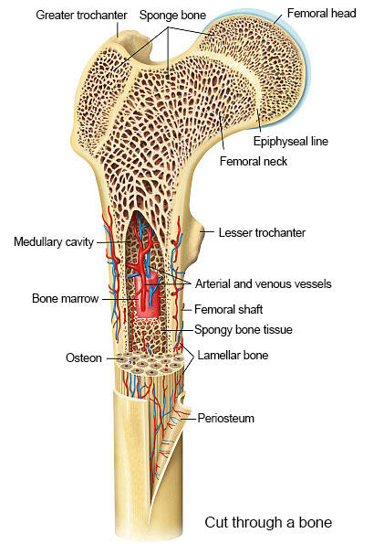
The following definitions are from (https://olemiss.edu/courses/bisc206/bones.html) (https://www.physio-pedia.com/Bone_Cortical_And_Cancellous) and doi 10.1186/s12882-020-01756-2
| Osteon | the structural unit (also called a Haversian System). Long cylinder parallel to long axis of the bone. |
| Lamellae | layers of matrix of the osteon. |
| Haversian Canal | runs up the center of the osteon, contains blood vessels, nerves. |
| Perforating Canal | also called Volkmann's canals, perpendicular to Haversian canals, supply Haversian canals. Both canal types are lined with endosteum. |
| Lacunae | spaces between lamellae. |
| Osteocytes | mature bone cells in the lacunae. |
| Canaliculi | tiny canals that connect all the lacunae. |
| Circumferential Lamellae | Layers of bone matrix that go all the way around the bone. |
| Interstitial Lamellae | Interstitial lamellae fill in between osteons. |
| Cortical bone | Main stress bearing material. A dense, low-porosity and less metabolically active tissue, |
| Cancellous/trabecular bone | A honeycomb-like trabecular network located in the medullary cavity with a larger remodeling area and higher turnover rate |
| Haversian canals | Tubes formed by lamellae that surround blood vessels and nerve fibers allowing information and materials to reach the osteocytes |
| Periosteum | The outside layer of the cortical bone |
Moment and stresses in shear loaded beams
- Bones and buildings both need to resist shear forces, ie forces causing the material to slide rather than pull apart.
- Analysis of a beam gives insight into both tensile/compressive forces and shear forces.
- Can considering two types of beam
- Cantilever, supported on one end with a force and torque from a 'wall'
- Bridge, supported at both ends
- Can identify the forces in the material and from this identify how much they will deform with a load
- The forces, along with the Young's modulus and a second moment of area (see below) allows for prediction of the structures deflection.
Shear force and bending moment diagrams
We can consider the internal forces in a material. These are not homogeneous, rather they vary along the length and through the height of the beam

The internal forces can be analysed in a cantilever beam. A first insight is possible by considering the how the shear force and bending moment vairy along the beam. Note that the bending moment arises from tensile and compressive forces along the notional 'cut' but these forces are agregated into a single moment.

The shear force and bending moment of a bridge structure (double supported) can likewise be analysed. In this case it may be helpful to consider a load force $F_L$ that occurs some percentage $p/L$ along the beam. For example if $p/L=0.2$, i.e. 20% then $F_A=0.8F_L$ and $F_B=0.2F_L$. This simplifies the calculation of $F_A$ and $F_B$ that are needed to work out both the shear force and the bending moment. These will be calculate for the left most face. Equal and oposite forces for the right face of the 'cut' must be in place for the beam to remain in place.
Formulae for beam deflection and rotation
Further analysis of the forces in the beam allow a calculation of the end difflection and slope. These calculations may provide a rapid first estimate of forces in, for example, an internal prosthesis to facilitate material selection.
This force/bending analysis is known as Euler-Bernoulli beam theory. This allows standard formulae to be calculated as shown in the figure
below.Note $E$ is the Youngs/Elastic modulus, and $I$ is the second moment of area of the beam/bone cross-section (See section on Second moment of area). The second moment of area will be along an axis out of the page that passes through what is called the 'neutral axis' where there are no tensile/compressive forces.


Second moment of area
The defintion of $I$ of some 2 dimensional region $\mathcal{R}$ about some axis $x-x$ is
\[ I_{xx}=\int_\mathcal{R} \rho^2 dA \]where $\rho$ is the perpendicular distance to axis $x-x$
In cartesian coordinates for the $x-y$ coordinate frame this is
\[ I_{xx}=\int_{y_1}^{y_2}\int_{x_1}^{x_2} y^2 dx dy \]Often the order of integration does not matter as long as the limits of integration are preserved so
\[ I_{xx}=\int_{x_1}^{x_2}\int_{y_1}^{y_2} y^2 dy dx \]Table of some second moments of area
All the following shapes have the centre of area at the origin of the coordinate system, hence can be used with the parallel axis theorem to find the second moment of area of more complex shapes.
| A filled ellipse |  | $I_x=\frac\pi4ab^3\quad I_y=\frac\pi4a^3b$ |
| A circle |  | $I_x=I_y=\frac\pi4r^4$ |
| An annulus |  | $I_x=\frac\pi4\left(r_2^4-r_1^4\right)$ |
| A rectangle |  | $I_x=\frac{bh^3}{12}\quad I_y=\frac{b^3h}{12}$ |
| A circle segment/sector |  | $I_x=(\theta - \sin\theta)\frac{r^4}{8}\quad$ valid only for $0<\theta<\pi$ |
Addition and subtraction
Second moment of areas can be added and subtracted provided they are all refered to the same axes. To do this it may be necessary to invoke the parallel axis theorem
Parallel axis Theorem
If the second moment of area of a shape about the centre of area is $I_x$ then the second moment of area of that same shape about a parallel axis displaced by a distance $d$ from the principal axis is
\[ I_{x'}=I_{x}+Ad^{2} \]Where $A$ is the area of the shape
10/10/2023